VoIP Protocols: H.323 Call Flow
Vladimír Toncar
In a recent piece, we introduced the H.323 protocol as such, and described the role of individual components of the H.323 network. Now, let's have a closer look at signalling and describe the typical H.323 call flow. We will describe the basic H.323 version 1 call signalling without additional signalling optimizations (We will deal with these optimizations in another article).
We will assume a network that uses a gatekeeper (see the H.323 Introduction for the explanation of the gatekeeper's role) and will also assume the signalling flows via the gatekeeper (also known as the gatekeeper-routed call model). This is really the more complex situation but I believe it is helpful to have the whole picture and the call without a gatekeeper would be a straightforward simplification of the example we show here.
So, let's have two endpoints (IP phones) and a gatekeeper. The telephone numbers assigned to the endpoints are 121 and 122, respectively. Let us assume the two endpoints are registered with the gatekeeper.
Now, someone at the number 121 dials "122". This is what is going to happen:
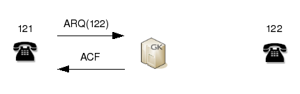
1. The endpoint that initiates the call knows the called number (122) but it does not know the IP address associated with that number. At the same time, since it is registered with the gatekeeper, it must ask the gatekeeper for a permission to place the call. It does so by sending the Admission Request message to the gatekeeper. The Admission Request (ARQ) will contain the called number (122), indicating to the gatekeeper that the endpoint needs to have the number resolved to an IP address. As we said in the introduction, the protocol used to communicate with the gatekeeper is H.225.0-RAS which uses UDP as the underlying transport protocol.
2. The gatekeeper will check it's database of registered endpoints whether it contains the number 122. If so, the gatekeeper will check if 121 is allowed to call 122 and if it is possible to place the call — for example, if there is enough bandwidth (a bandwidth limit could be configured on the gatekeeper for a subnet that's connected via some WAN link). After that, the gatekeeper will form an answer — the message Admission Confirm (ACF) with an IP address and send the ACF to the calling endpoint. If the gatekeeper supports the so called Gatekeeper-routed call model, the IP address in the ACF will be an address on the gatekeeper. Otherwise, with the Direct call model, the address will be the call signalling address of the endpoint 122.
Steps 1 and 2 are shown in Figure A.
 |
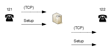
3. The enpoint 121 will now open a call signalling channel to the address provided by the gatekeeper in the ACF message. The call signalling messages are sent over TCP and the protocol is H.225.0, embedded in Q.931 (we will denote this as Q.931/H.225.0). With the gatekeeper-routed call model, the endpoint 121 will open a TCP channel to the gatekeeper and send the Q.931/H.225.0 message Setup. The gatekeeper will in turn open a second TCP channel to the endpoint 122 and forward the Setup message. The gatekeeper-routed call model gives the gatekeeper the possibility to inspect and sometimes alter the passing signalling messages. The gatekeeper thus has a better control of active calls.
The activities in step 3 are shown in Figure B.
 |
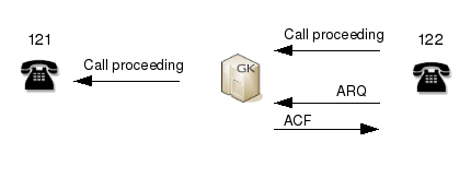
4. The endpoint 122 will first respond with the Q.931/H.225.0 message Call Proceeding to indicate it has started working on setting up the call and the gatekeeper will forward the message to the calling endpoint. After that, 122 will ask the gatekeeper for a call permission (Admission Request, ARQ) and the gatekeeper will respond with Admission Confirm (ACF). This is shown in Figure C.
 |
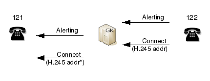
5. The called telephone (122) starts ringing and this is signalled to the other party with the Q.931/H.225.0 message Alerting, as shown in Figure D.
6. The called party picks up the handset and the endpoint can signal the call has been accepted. This is done by sending the Q.931/H.225.0 message Connect. At this point, the parties will need to negotiate parameters for audio (and optionally video) channels. The protocol H.245 is used for this negotiation. In the default case, H.245 will need another TCP channel, so the endpoint 122 will insert its H.245 address (the IP address and port where it listens for H.245 connections) into the Connect message. Since the call uses gatekeeper-routed call model, the gatekeeper will usually replace the H.245 address with it own H.245 address, so that it can inspect H.245 messages as well. In Figure D, the rewritten H.245 address is denoted with asterisk.
 |
7. The calling endpoint opens a TCP channel to the H.245 address it has received in the Connect message, and the gatekeeper will establish the second "half" of the H.245 signalling channel. The endpoints can start exchanging H.245 messages. The H.245 negotiation has three parts:
- Deciding which endpoint is the "master" and which is the "slave". This has more of an importance for conferences with multiple participants, rather than for a two-party call. It is done nonetheless.
- Exchanging information about the capability set of each party. The endpoints need to know what audio and video codecs the other party supports.
- Deciding about the actual parameters for the audio (and optionally video) channels - i.e. what codecs will be used and what are the IP addresses and ports for the RTP streams. This is known as the negotiation of logical channels.
8. Finally, the two endpoints can start sending the RTP streams and the two people will hear one another. Note that each of the two directions can be encoded with a different codec.
The steps 7 and 8 are shown in Figure E.
 |
Let's now have a look at what happens when the call is over:
- The two endpoints stop sending the RTP streams. They announce the closing of logical channels (H.245 Request CloseLogicalChannel).
- The H.245 signalling channel is closed (H.245 command message EndSessionCommand followed by closing of the TCP connection).
- The main signalling connection is also closed — the endpoints exchange Q.931/H.225.0 messages ReleaseComplete and the TCP connection is closed.
- Each of the two endpoints informs the gatekeeper about the completed call with the H.225.0-RAS message Disengage Request (DRQ) and the gatekeeper confirms with Disengage Confirm (DCF).
- And now the call is really over!
This concludes the description of H.323 call signalling. The aim of this text was to give you a general overview. If you need to know more, it's best to check the H.323 standard or, if you prefer the practical method, use Ethereal/Wireshark to capture packets and inspect the details yourself.
Next section: VoIP Protocols: H.323 Call Signalling Optimizations